Subtractor
Circuit that performs subtraction
In electronics, a subtractor is a digital circuit that performs subtraction of numbers, and it can be designed using the same approach as that of an adder. The binary subtraction process is summarized below. As with an adder, in the general case of calculations on multi-bit numbers, three bits are involved in performing the subtraction for each bit of the difference: the minuend (




,

where ⊕ represents exclusive or.
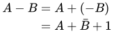
Subtractors are usually implemented within a binary adder for only a small cost when using the standard two's complement notation, by providing an addition/subtraction selector to the carry-in and to invert the second operand.
(definition of two's complement notation)
01Half subtractor
The half subtractors can be designed through the combinational Boolean logic circuits [2] as shown in Figure 1 and 2. The half subtractor is a combinational circuit which is used to perform subtraction of two bits. It has two inputs, the minuend 


.
This is an important distinction to make since subtraction itself is not commutative, but the difference bit
The truth table for the half subtractor is:
| Inputs | Outputs | ||
|---|---|---|---|
| X | Y | D | Bout |
| 0 | 0 | 0 | 0 |
| 0 | 1 | 1 | 1 |
| 1 | 0 | 1 | 0 |
| 1 | 1 | 0 | 0 |
Using the table above and a Karnaugh map, we find the following logic equations for

Consequently, a simplified half-subtract circuit, advantageously avoiding crossed traces in particular as well as a negate gate is:
X ── XOR ─┬─────── |X-Y|, is 0 if X equals Y, 1 otherwise ┌──┘ └──┐ Y ─┴─────── AND ── borrow, is 1 if Y > X, 0 otherwisewhere lines to the right are outputs and others (from the top, bottom or left) are inputs.


02Full subtractor
The full subtractor is a combinational circuit which is used to perform subtraction of three input bits: the minuend 



The truth table for the full subtractor is:
| Inputs | Outputs | |||
|---|---|---|---|---|
| X | Y | Bin | D | Bout |
| 0 | 0 | 0 | 0 | 0 |
| 0 | 0 | 1 | 1 | 1 |
| 0 | 1 | 0 | 1 | 1 |
| 0 | 1 | 1 | 0 | 1 |
| 1 | 0 | 0 | 1 | 0 |
| 1 | 0 | 1 | 0 | 0 |
| 1 | 1 | 0 | 0 | 0 |
| 1 | 1 | 1 | 1 | 1 |
Therefore the equation is:



Sources and credits
This article is adapted from the Wikipedia article “Subtractor”, written by its contributors and licensed under CC BY-SA 4.0. Fathomly has changed the layout, removed citation markers, navigation and maintenance notices, and adjusted punctuation. This adapted version is shared under the same license. For references, see the original article.
Images, from Wikimedia Commons:
- Half Subtractor Vektor.svg by MrOerni, CC0
- Half subtractor using NAND.jpg by Nitianabhigyan, CC BY-SA 4.0
- Full-sub-Fixed.svg by 48panda, CC BY-SA 4.0
Fathomly is not affiliated with or endorsed by the Wikimedia Foundation. Spotted a problem? Tell us.