Reference articles on history, science, culture and more
Encyclopedia

Stokes parameters

Set of values that describe the polarization state of electromagnetic radiation

Image credit is listed at the end of this article.

The Stokes parameters are a set of values that describe the polarization state of electromagnetic radiation. They were defined by George Gabriel Stokes in 1851, as a mathematically convenient alternative to the more common description of incoherent or partially polarized radiation in terms of its total intensity (I), (fractional) degree of polarization (p), and the shape parameters of the polarization ellipse. The effect of an optical system on the polarization of light can be determined by constructing the Stokes vector for the input light and applying Mueller calculus, to obtain the Stokes vector of the light leaving the system. They can be determined from directly observable phenomena. The original Stokes paper was discovered independently by Francis Perrin in 1942 and by Subrahamanyan Chandrasekhar in 1947, who named it as the Stokes parameters.

01Definitions

The relationship of the Stokes parameters S0, S1, S2, S3 to intensity and polarization ellipse parameters is shown in the equations below and the figure on the right.
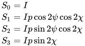
{\begin{aligned}S_{0}&=I\\S_{1}&=Ip\cos 2\psi \cos 2\chi \\S_{2}&=Ip\sin 2\psi \cos 2\chi \\S_{3}&=Ip\sin 2\chi \end{aligned}}

Here Ip, 2\psi and 2\chi are the spherical coordinates of the three-dimensional vector of cartesian coordinates (S_{1},S_{2},S_{3}). I is the total intensity of the beam, and p is the degree of polarization, constrained by 0\leq p\leq 1. The factor of two before \psi represents the fact that any polarization ellipse is indistinguishable from one rotated by 180°, while the factor of two before \chi indicates that an ellipse is indistinguishable from one with the semi-axis lengths swapped accompanied by a 90° rotation. The phase information of the polarized light is not recorded in the Stokes parameters. The four Stokes parameters are sometimes denoted I, Q, U and V, respectively.

Given the Stokes parameters, one can solve for the spherical coordinates with the following equations:
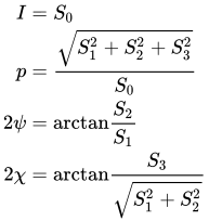
{\begin{aligned}I&=S_{0}\\p&={\frac {\sqrt {S_{1}^{2}+S_{2}^{2}+S_{3}^{2}}}{S_{0}}}\\2\psi &=\mathrm {arctan} {\frac {S_{2}}{S_{1}}}\\2\chi &=\mathrm {arctan} {\frac {S_{3}}{\sqrt {S_{1}^{2}+S_{2}^{2}}}}\\\end{aligned}}

Stokes vectors

The Stokes parameters are often combined into a vector, known as the Stokes vector:
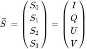
{\vec {S}}\ ={\begin{pmatrix}S_{0}\\S_{1}\\S_{2}\\S_{3}\end{pmatrix}}={\begin{pmatrix}I\\Q\\U\\V\end{pmatrix}}

The Stokes vector can describe the state of unpolarized, partially polarized, and fully polarized light. For comparison, the Jones vector only describes fully polarized light, but is more useful for problems involving coherent light.

Note that there is an ambiguous sign for the V component depending on the physical convention used. In practice, there are two separate conventions used, either defining the Stokes parameters when looking down the beam towards the source (opposite the direction of light propagation) or looking down the beam away from the source (coincident with the direction of light propagation). These two conventions result in different signs for V, and a convention must be chosen and adhered to.

Examples

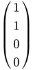
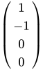
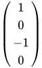
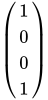
Below are shown some Stokes vectors for common states of polarization of light.

{\begin{pmatrix}1\\1\\0\\0\end{pmatrix}}Linearly polarized (horizontal)
{\begin{pmatrix}1\\-1\\0\\0\end{pmatrix}}Linearly polarized (vertical)
{\begin{pmatrix}1\\0\\1\\0\end{pmatrix}}Linearly polarized (+45°)
{\begin{pmatrix}1\\0\\-1\\0\end{pmatrix}}Linearly polarized (−45°)
{\begin{pmatrix}1\\0\\0\\1\end{pmatrix}}Right-hand circularly polarized
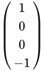
{\begin{pmatrix}1\\0\\0\\-1\end{pmatrix}}Left-hand circularly polarized
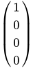
{\begin{pmatrix}1\\0\\0\\0\end{pmatrix}}Unpolarized
Polarisation ellipse, showing the relationship to the Poincaré sphere parameters ψ and χ.

02Alternative explanation

A monochromatic plane wave is specified by its propagation vector, {\vec {k}}, and the complex amplitudes of the electric field, E_{1} and E_{2}, in a basis ({\hat {\epsilon }}_{1},{\hat {\epsilon }}_{2}). The pair (E_{1},E_{2}) is called a Jones vector. Alternatively, one may specify the propagation vector, the phase, \phi, and the polarization state, \Psi, where \Psi is the curve traced out by the electric field as a function of time in a fixed plane. The most familiar polarization states are linear and circular, which are degenerate cases of the most general state, an ellipse.

One way to describe polarization is by giving the semi-major and semi-minor axes of the polarization ellipse, its orientation, and the direction of rotation (See the above figure). The Stokes parameters I, Q, U, and V, provide an alternative description of the polarization state which is experimentally convenient because each parameter corresponds to a sum or difference of measurable intensities. The next figure shows examples of the Stokes parameters in degenerate states.

Definitions

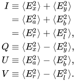
The Stokes parameters are defined by
{\begin{aligned}I&\equiv \langle E_{x}^{2}\rangle +\langle E_{y}^{2}\rangle \\&=\langle E_{a}^{2}\rangle +\langle E_{b}^{2}\rangle \\&=\langle E_{r}^{2}\rangle +\langle E_{l}^{2}\rangle ,\\Q&\equiv \langle E_{x}^{2}\rangle -\langle E_{y}^{2}\rangle ,\\U&\equiv \langle E_{a}^{2}\rangle -\langle E_{b}^{2}\rangle ,\\V&\equiv \langle E_{r}^{2}\rangle -\langle E_{l}^{2}\rangle .\end{aligned}}

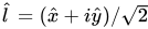
where the subscripts refer to three different bases of the space of Jones vectors: the standard Cartesian basis ({\hat {x}},{\hat {y}}), a Cartesian basis rotated by 45° ({\hat {a}},{\hat {b}}), and a circular basis ({\hat {l}},{\hat {r}}). The circular basis is defined so that {\hat {l}}=({\hat {x}}+i{\hat {y}})/{\sqrt {2}}, {\hat {r}}=({\hat {x}}-i{\hat {y}})/{\sqrt {2}}.

The symbols ⟨⋅⟩ represent expectation values. The light can be viewed as a random variable taking values in the space C2 of Jones vectors (E_{1},E_{2}). Any given measurement yields a specific wave (with a specific phase, polarization ellipse, and magnitude), but it keeps flickering and wobbling between different outcomes. The expectation values are various averages of these outcomes. Intense, but unpolarized light will have I > 0 but Q = U = V = 0, reflecting that no polarization type predominates. A convincing waveform is depicted at the article on coherence.

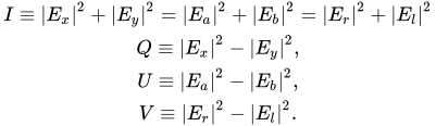
The opposite would be perfectly polarized light which, in addition, has a fixed, nonvarying amplitude, a pure sine curve. This is represented by a random variable with only a single possible value, say (E_{1},E_{2}). In this case one may replace the brackets by absolute value bars, obtaining a well-defined quadratic map
{\begin{matrix}I\equiv |E_{x}|^{2}+|E_{y}|^{2}=|E_{a}|^{2}+|E_{b}|^{2}=|E_{r}|^{2}+|E_{l}|^{2}\\Q\equiv |E_{x}|^{2}-|E_{y}|^{2},\\U\equiv |E_{a}|^{2}-|E_{b}|^{2},\\V\equiv |E_{r}|^{2}-|E_{l}|^{2}.\end{matrix}}

from the Jones vectors to the corresponding Stokes vectors; more convenient forms are given below. The map takes its image in the cone defined by |I |2 = |Q |2 + |U |2 + |V |2, where the purity of the state satisfies p = 1 (see below).

The next figure shows how the signs of the Stokes parameters are determined by the helicity and the orientation of the semi-major axis of the polarization ellipse. Note that the "handedness" of the V-parametre is accidentally reversed in the image below. Positive V is right-handed, negative V is left-handed (see e.g., pp. 46-53 of "Absorption and Scattering of Light by Small Particles" by Bohren & Huffman).

Representations in fixed bases

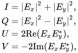
In a fixed ({\hat {x}},{\hat {y}}) basis, the Stokes parameters when using an increasing phase convention are

{\begin{aligned}I&=|E_{x}|^{2}+|E_{y}|^{2},\\Q&=|E_{x}|^{2}-|E_{y}|^{2},\\U&=2\mathrm {Re} (E_{x}E_{y}^{*}),\\V&=-2\mathrm {Im} (E_{x}E_{y}^{*}),\\\end{aligned}}

while for ({\hat {a}},{\hat {b}}), they are

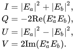
{\begin{aligned}I&=|E_{a}|^{2}+|E_{b}|^{2},\\Q&=-2\mathrm {Re} (E_{a}^{*}E_{b}),\\U&=|E_{a}|^{2}-|E_{b}|^{2},\\V&=2\mathrm {Im} (E_{a}^{*}E_{b}).\\\end{aligned}}

and for ({\hat {l}},{\hat {r}}), they are

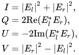
{\begin{aligned}I&=|E_{l}|^{2}+|E_{r}|^{2},\\Q&=2\mathrm {Re} (E_{l}^{*}E_{r}),\\U&=-2\mathrm {Im} (E_{l}^{*}E_{r}),\\V&=|E_{r}|^{2}-|E_{l}|^{2}.\\\end{aligned}}
The Poincaré sphere is the parametrisation of the last three Stokes' parameters in spherical coordinates.

03Properties

For purely monochromatic coherent radiation, it follows from the above equations that

Q^{2}+U^{2}+V^{2}=I^{2},

whereas for the whole (non-coherent) beam radiation, the Stokes parameters are defined as averaged quantities, and the previous equation becomes an inequality:

Q^{2}+U^{2}+V^{2}\leq I^{2}.

However, we can define a total polarization intensity I_{p}, so that

Q^{2}+U^{2}+V^{2}=I_{p}^{2},

where I_{p}/I is the total polarization fraction.

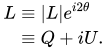
Let us define the complex intensity of linear polarization to be
{\begin{aligned}L&\equiv |L|e^{i2\theta }\\&\equiv Q+iU.\\\end{aligned}}

Under a rotation \theta \rightarrow \theta +\theta ' of the polarization ellipse, it can be shown that I and V are invariant, but

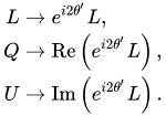
{\begin{aligned}L&\rightarrow e^{i2\theta '}L,\\Q&\rightarrow {\mbox{Re}}\left(e^{i2\theta '}L\right),\\U&\rightarrow {\mbox{Im}}\left(e^{i2\theta '}L\right).\\\end{aligned}}

With these properties, the Stokes parameters may be thought of as constituting three generalized intensities:

{\begin{aligned}I&\geq 0,\\V&\in \mathbb {R} ,\\L&\in \mathbb {C} ,\\\end{aligned}}

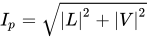
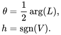
where I is the total intensity, |V| is the intensity of circular polarization, and |L| is the intensity of linear polarization. The total intensity of polarization is I_{p}={\sqrt {|L|^{2}+|V|^{2}}}, and the orientation and sense of rotation are given by

{\begin{aligned}\theta &={\frac {1}{2}}\arg(L),\\h&=\operatorname {sgn} (V).\\\end{aligned}}

Since Q={\mbox{Re}}(L) and U={\mbox{Im}}(L), we have

{\begin{aligned}|L|&={\sqrt {Q^{2}+U^{2}}},\\\theta &={\frac {1}{2}}\operatorname {atan2} (U,Q).\\\end{aligned}}

In the last formula, the two-argument arctangent function atan2 computes the principal argument of the complex number Q+iU.

Depiction of the polarization states on Poincaré sphere

04Relation to the polarization ellipse

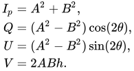
In terms of the parameters of the polarization ellipse, the Stokes parameters are
{\begin{aligned}I_{p}&=A^{2}+B^{2},\\Q&=(A^{2}-B^{2})\cos(2\theta ),\\U&=(A^{2}-B^{2})\sin(2\theta ),\\V&=2ABh.\\\end{aligned}}

Inverting the previous equation gives
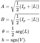
{\begin{aligned}A&={\sqrt {{\frac {1}{2}}(I_{p}+|L|)}}\\B&={\sqrt {{\frac {1}{2}}(I_{p}-|L|)}}\\\theta &={\frac {1}{2}}\arg(L)\\h&=\operatorname {sgn} (V).\\\end{aligned}}

05Measurement

The Stokes parameters (and thus the polarization of some electromagnetic radiation) can be directly determined from observation. Using a linear polarizer and a quarter-wave plate, the following system of equations relating the Stokes parameters to measured intensity can be obtained:
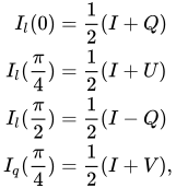
{\begin{aligned}I_{l}(0)&={\frac {1}{2}}(I+Q)\\I_{l}({\frac {\pi }{4}})&={\frac {1}{2}}(I+U)\\I_{l}({\frac {\pi }{2}})&={\frac {1}{2}}(I-Q)\\I_{q}({\frac {\pi }{4}})&={\frac {1}{2}}(I+V),\\\end{aligned}}

where I_{l}(\theta ) is the irradiance of the radiation at a point when the linear polarizer is rotated at an angle of \theta, and similarly I_{q}(\theta ) is the irradiance at a point when the quarter-wave plate is rotated at an angle of \theta. A system can be implemented using both plates at once at different angles to measure the parameters. This can give a more accurate measure of the relative magnitudes of the parameters (which is often the main result desired) due to all parameters being affected by the same losses.

06Relationship to Hermitian operators and quantum mixed states

From a geometric and algebraic point of view, the Stokes parameters stand in one-to-one correspondence with the closed, convex, 4-real-dimensional cone of nonnegative Hermitian operators on the Hilbert space C2. The parameter I serves as the trace of the operator, whereas the entries of the matrix of the operator are simple linear functions of the four parameters I, Q, U, V, serving as coefficients in a linear combination of the Stokes operators. The eigenvalues and eigenvectors of the operator can be calculated from the polarization ellipse parameters I, p, ψ, χ.

The Stokes parameters with I set equal to 1 (i.e. the trace 1 operators) are in one-to-one correspondence with the closed unit 3-dimensional ball of mixed states (or density operators) of the quantum space C2, whose boundary is the Bloch sphere. The Jones vectors correspond to the underlying space C2, that is, the (unnormalized) pure states of the same system. Note that the overall phase (i.e. the common phase factor between the two component waves on the two perpendicular polarization axes) is lost when passing from a pure state |φ⟩ to the corresponding mixed state |φ⟩⟨φ|, just as it is lost when passing from a Jones vector to the corresponding Stokes vector.

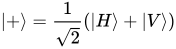
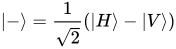
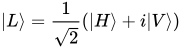
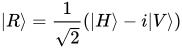
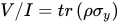
In the basis of horizontal polarization state |H\rangle and vertical polarization state |V\rangle, the +45° linear polarization state is |+\rangle ={\frac {1}{\sqrt {2}}}(|H\rangle +|V\rangle ), the -45° linear polarization state is |-\rangle ={\frac {1}{\sqrt {2}}}(|H\rangle -|V\rangle ), the left hand circular polarization state is |L\rangle ={\frac {1}{\sqrt {2}}}(|H\rangle +i|V\rangle ), and the right hand circular polarization state is |R\rangle ={\frac {1}{\sqrt {2}}}(|H\rangle -i|V\rangle ). It's easy to see that these states are the eigenvectors of Pauli matrices, and that the normalized Stokes parameters (U/I, V/I, Q/I) correspond to the coordinates of the Bloch vector (a_{x}, a_{y}, a_{z}). Equivalently, we have U/I=tr\left(\rho \sigma _{x}\right), V/I=tr\left(\rho \sigma _{y}\right), Q/I=tr\left(\rho \sigma _{z}\right), where \rho is the density matrix of the mixed state.

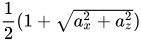
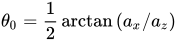
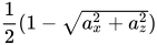
Generally, a linear polarization at angle θ has a pure quantum state |\theta \rangle =\cos {\theta }|H\rangle +\sin {\theta }|V\rangle; therefore, the transmittance of a linear polarizer/analyzer at angle θ for a mixed state light source with density matrix \rho ={\frac {1}{2}}\left(I+a_{x}\sigma _{x}+a_{y}\sigma _{y}+a_{z}\sigma _{z}\right) is tr(\rho |\theta \rangle \langle \theta |)={\frac {1}{2}}\left(1+a_{x}\sin {2\theta }+a_{z}\cos {2\theta }\right), with a maximum transmittance of {\frac {1}{2}}(1+{\sqrt {a_{x}^{2}+a_{z}^{2}}}) at \theta _{0}={\frac {1}{2}}\arctan {(a_{x}/a_{z})} if a_{z}>0, or at \theta _{0}={\frac {1}{2}}\arctan {(a_{x}/a_{z})}+{\frac {\pi }{2}} if a_{z}<0; the minimum transmittance of {\frac {1}{2}}(1-{\sqrt {a_{x}^{2}+a_{z}^{2}}}) is reached at the perpendicular to the maximum transmittance direction. Here, the ratio of maximum transmittance to minimum transmittance is defined as the extinction ratio ER=(1+DOLP)/(1-DOLP), where the degree of linear polarization is DOLP={\sqrt {a_{x}^{2}+a_{z}^{2}}}. Equivalently, the formula for the transmittance can be rewritten as A\cos ^{2}{(\theta -\theta _{0})}+B, which is an extended form of Malus's law; here, A,B are both non-negative, and is related to the extinction ratio by ER=(A+B)/B. Two of the normalized Stokes parameters can also be calculated by a_{x}=DOLP\sin {2\theta _{0}},\,a_{z}=DOLP\cos {2\theta _{0}},\,DOLP=(ER-1)/(ER+1).

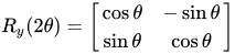
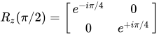
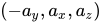
It's also worth noting that a rotation of polarization axis by angle θ corresponds to the Bloch sphere rotation operator R_{y}(2\theta )={\begin{bmatrix}\cos \theta &-\sin \theta \\\sin \theta &\cos \theta \end{bmatrix}}. For example, the horizontal polarization state |H\rangle would rotate to |\theta \rangle =\cos {\theta }|H\rangle +\sin {\theta }|V\rangle. The effect of a quarter-wave plate aligned to the horizontal axis is described by R_{z}(\pi /2)={\begin{bmatrix}e^{-i\pi /4}&0\\0&e^{+i\pi /4}\end{bmatrix}}, or equivalently the Phase gate S, and the resulting Bloch vector becomes (-a_{y},a_{x},a_{z}). With this configuration, if we perform the rotating analyzer method to measure the extinction ratio, we will be able to calculate a_{y} and also verify a_{z}. For this method to work, the fast axis and the slow axis of the waveplate must be aligned with the reference directions for the basis states.

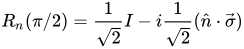
The effect of a quarter-wave plate rotated by angle θ can be determined by Rodrigues' rotation formula as R_{n}(\pi /2)={\frac {1}{\sqrt {2}}}I-i{\frac {1}{\sqrt {2}}}({\hat {n}}\cdot {\vec {\sigma }}), with {\hat {n}}={\hat {z}}\cos {2\theta }+{\hat {x}}\sin {2\theta }. The transmittance of the resulting light through a linear polarizer (analyzer plate) along the horizontal axis can be calculated using the same Rodrigues' rotation formula and focusing on its components on I and \sigma _{z}:
{\begin{aligned}T&=tr[R_{n}(\pi /2)\rho R_{n}(-\pi /2)|H\rangle \langle H|]\\&={\frac {1}{2}}\left[1+a_{y}\sin {2\theta }+({\hat {n}}\cdot {\vec {a}})\cos {2\theta }\right]\\&={\frac {1}{2}}\left[1+a_{y}\sin {2\theta }+(a_{x}\sin {2\theta }+a_{z}\cos {2\theta })\cos {2\theta }\right]\\&={\frac {1}{2}}\left(1+a_{y}\sin {2\theta }+DOLP\times {\frac {\cos {(4\theta -2\theta _{0})}+\cos {(2\theta _{0})}}{2}}\right)\end{aligned}}

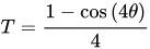
The above expression is the theory basis of many polarimeters. For unpolarized light, T=1/2 is a constant. For purely circularly polarized light, T has a sinusoidal dependence on angle θ with a period of 180 degrees, and can reach absolute extinction where T=0. For purely linearly polarized light, T has a sinusoidal dependence on angle θ with a period of 90 degrees, and absolute extinction is only reachable when the original light's polarization is at 90 degrees from the polarizer (i.e. a_{z}=-1). In this configuration, \theta _{0}={\frac {\pi }{2}} and T={\frac {1-\cos {(4\theta )}}{4}}, with a maximum of 1/2 at θ=45°, and an extinction point at θ=0°. This result can be used to precisely determine the fast or slow axis of a quarter-wave plate, for example, by using a polarizing beam splitter to obtain a linearly polarized light aligned to the analyzer plate and rotating the quarter-wave plate in between.

Similarly, the effect of a half-wave plate rotated by angle θ is described by R_{n}(\pi )=-i({\hat {n}}\cdot {\vec {\sigma }}), which transforms the density matrix to:

{\begin{aligned}R_{n}(\pi )\rho R_{n}(-\pi )&={\frac {1}{2}}\left(I+{\vec {a}}\cdot [-{\vec {\sigma }}+2{\hat {n}}({\hat {n}}\cdot {\vec {\sigma }})]\right)\\&={\frac {1}{2}}\left[I-{\vec {a}}\cdot {\vec {\sigma }}+2({\hat {n}}\cdot {\vec {a}})({\hat {n}}\cdot {\vec {\sigma }})\right]\end{aligned}}

The above expression demonstrates that if the original light is of pure linear polarization (i.e. a_{y}=0), the resulting light after the half-wave plate is still of pure linear polarization (i.e. without \sigma _{y} component) with a rotated major axis. Such rotation of the linear polarization has a sinusoidal dependence on angle θ with a period of 90 degrees.

Watch videos about Stokes parametersExplainers and documentaries on YouTube (opens in a new tab)

Sources and credits

This article is adapted from the Wikipedia article Stokes parameters, written by its contributors and licensed under CC BY-SA 4.0. Fathomly has changed the layout, removed citation markers, navigation and maintenance notices, and adjusted punctuation. This adapted version is shared under the same license. For references, see the original article.

Images, from Wikimedia Commons:

Fathomly is not affiliated with or endorsed by the Wikimedia Foundation. Spotted a problem? Tell us.