Precision rectifier
Electrical circuit
The precision rectifier, sometimes called a super diode, is an operational amplifier (opamp) circuit configuration that behaves like an ideal diode and rectifier.
The op-amp-based precision rectifier should not be confused with the power MOSFET-based active rectification ideal diode.
01Basic circuit
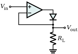
The basic circuit implementing such a feature is shown on the right, where 

The actual threshold is very close to zero, but is not zero. It equals the actual threshold of the diode, divided by the gain of the opamp.
This basic configuration has a problem, so it is not commonly used. When the input becomes (even slightly) negative, the opamp runs open-loop, as there is no feedback signal through the diode. For a typical opamp with high open-loop gain, the output saturates. If the input then becomes positive again, the op-amp has to get out of the saturated state before positive amplification can take place again. This change generates some ringing and takes some time, greatly reducing the frequency response of the circuit.

02Improved circuit
An alternative version is given on the right. In this case, when the input is greater than zero, D1 is off, and D2 is on, so the output is zero because the other end of 

This circuit has the benefit that the op-amp never goes into saturation, but its output must change by two diode voltage drops (about 1.2 V) each time the input signal crosses zero. Hence, the slew rate of the opamp and its frequency response (gain-bandwidth product) will limit high-frequency performance, especially for low signal levels, although an error of less than 1% at 100 kHz is possible.
Similar circuitry can be used to create a precision full-wave rectifier circuit.

03Peak detector
With a little modification, the basic precision rectifier can be used for detecting signal level peaks. In the following circuit, a capacitor retains the peak voltage level of the signal, and a switch is used for resetting the detected level. When the input Vin exceeds Vc (voltage across capacitor), the diode is forward-biased and the circuit becomes a voltage follower. Consequently, the output voltage Vo follows Vin as long as Vin exceeds Vc. When Vin drops below Vc, the diode becomes reverse-biased and the capacitor holds the charge until Vin again attains a value greater than Vc.

Sources and credits
This article is adapted from the Wikipedia article “Precision rectifier”, written by its contributors and licensed under CC BY-SA 4.0. Fathomly has changed the layout, removed citation markers, navigation and maintenance notices, and adjusted punctuation. This adapted version is shared under the same license. For references, see the original article.
Images, from Wikimedia Commons:
- Op-Amp Precision Rectifier.svg by Inductiveload, Public domain
- Op-Amp Precision Rectifier (Improved).svg by Inductiveload, Public domain
- Transfer function of an improved super diode.svg by Alessio Damato, CC BY-SA 3.0
- PeakDet.svg by Alessio Damato, CC BY-SA 3.0
Fathomly is not affiliated with or endorsed by the Wikimedia Foundation. Spotted a problem? Tell us.