Murray loop bridge

The Murray loop bridge is a bridge circuit used for locating faults in underground or underwater cables. It has been used for more than 100 years but is being replaced by the more precise time-domain reflectometer.
One end of the faulted cable is connected through a pair of resistors to the voltage source. Also a null detector is connected. The other end of the cable is shorted. The bridge is brought to balance by changing the values of RB1 and RB2, which is achieved when:
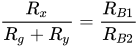
which is equivalent to:
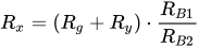
The value of resistance Rx is proportional the length Lx, thus the location of the fault can be calculated:
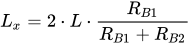
where L is the total length of the cable under test - a value proportional to Rg.
The method assumes a single fault exists, of low resistance compared with the undamaged cable insulation resistance, and that the cable conductors have uniform resistance per unit length.
01Varley loop
The similar Varley loop uses fixed resistors for RB1 and RB2, and inserts a variable resistor in the faulted leg. Test sets for cable testing can be connected for either bridge technique. If the fault resistance is high, the sensitivity of the Murray bridge is reduced and the Varley loop may be more suitable.

Sources and credits
This article is adapted from the Wikipedia article “Murray loop bridge”, written by its contributors and licensed under CC BY-SA 4.0. Fathomly has changed the layout, removed citation markers, navigation and maintenance notices, and adjusted punctuation. This adapted version is shared under the same license. For references, see the original article.
Images, from Wikimedia Commons:
- Murray loop bridge.svg by Zureks, CC BY-SA 3.0
- Leeds & Northrup Type S Test Set No. 5300.jpg by Butch, CC BY-SA 3.0
Fathomly is not affiliated with or endorsed by the Wikimedia Foundation. Spotted a problem? Tell us.
