Moore machine
Finite-state machine whose output values are determined only by its current state
In the theory of computation, a Moore machine is a finite-state machine whose current output values are determined only by its current state. This is in contrast to a Mealy machine, whose output values are determined both by its current state and by the values of its inputs. Like other finite state machines, in Moore machines, the input typically influences the next state. Thus the input may indirectly influence subsequent outputs, but not the current or immediate output. The Moore machine is named after Edward F. Moore, who presented the concept in a 1956 paper, “Gedanken-experiments on Sequential Machines.”
01Formal definition
A Moore machine can be defined as a 6-tuple 
- A finite set of states
- A start state (also called initial state)
which is an element of
- A finite set called the input alphabet
- A finite set called the output alphabet
- A transition function
mapping a state and the input alphabet to the next state
- An output function
mapping each state to the output alphabet


"Evolution across time" is realized in this abstraction by having the state machine consult the time-changing input symbol at discrete "timer ticks" 
A Moore machine can be regarded as a restricted type of finite-state transducer.

02Visual representation
Table
A state transition table is a table listing all the triples in the transition relation
Diagram
The state diagram for a Moore machine, or Moore diagram, is a state diagram that associates an output value with each state.
03Relationship with Mealy machines
As Moore and Mealy machines are both types of finite-state machines, they are equally expressive: either type can be used to parse a regular language.
The difference between Moore machines and Mealy machines is that in the latter, the output of a transition is determined by the combination of current state and current input (


- for a Moore machine, each node (state) is labeled with an output value;
- for a Mealy machine, each arc (transition) is labeled with an output value.
Every Moore machine 


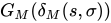


However, not every Mealy machine can be converted to an equivalent Moore machine. Some can be converted only to an almost equivalent Moore machine, with outputs shifted in time. This is due to the way that state labels are paired with transition labels to form the input/output pairs. Consider a transition 


04Examples
Types according to number of inputs/outputs.
Simple
Simple Moore machines have one input and one output:
- edge detector using XOR
- binary adding machine
- clocked sequential systems (a restricted form of Moore machine where the state changes only when the global clock signal changes)
Most digital electronic systems are designed as clocked sequential systems. Clocked sequential systems are a restricted form of Moore machine where the state changes only when the global clock signal changes. Typically the current state is stored in flip-flops, and a global clock signal is connected to the "clock" input of the flip-flops. Clocked sequential systems are one way to solve metastability problems. A typical electronic Moore machine includes a combinational logic chain to decode the current state into the outputs (lambda). The instant the current state changes, those changes ripple through that chain, and almost instantaneously the output gets updated. There are design techniques to ensure that no glitches occur on the outputs during that brief period while those changes are rippling through the chain, but most systems are designed so that glitches during that brief transition time are ignored or are irrelevant. The outputs then stay the same indefinitely (LEDs stay bright, power stays connected to the motors, solenoids stay energized, etc.), until the Moore machine changes state again.
Worked example
A sequential network has one input and one output. The output becomes 1 and remains 1 thereafter when at least two 0's and two 1's have occurred as inputs.
A Moore machine with nine states for the above description is shown on the right. The initial state is state A, and the final state is state I. The state table for this example is as follows:
| Current state | Input | Next state | Output |
|---|---|---|---|
| A | 0 | D | 0 |
| 1 | B | ||
| B | 0 | E | 0 |
| 1 | C | ||
| C | 0 | F | 0 |
| 1 | C | ||
| D | 0 | G | 0 |
| 1 | E | ||
| E | 0 | H | 0 |
| 1 | F | ||
| F | 0 | I | 0 |
| 1 | F | ||
| G | 0 | G | 0 |
| 1 | H | ||
| H | 0 | H | 0 |
| 1 | I | ||
| I | 0 | I | 1 |
| 1 | I |
Complex
More complex Moore machines can have multiple inputs as well as multiple outputs.
05Gedanken-experiments
In Moore's 1956 paper "Gedanken-experiments on Sequential Machines", the 


At the end of the paper, in Section "Further problems", the following task is stated:
Another directly following problem is the improvement of the bounds given at the theorems 8 and 9.
Moore's Theorem 8 is formulated as:
Given an arbitrary
which determines the state of
In 1957, A. A. Karatsuba proved the following two theorems, which completely solved Moore's problem on the improvement of the bounds of the experiment length of his "Theorem 8".
Theorem A. If
through which one may determine the state of
Theorem B. There exists an
Theorems A and B were used for the basis of the course work of a student of the fourth year, A. A. Karatsuba, "On a problem from the automata theory", which was distinguished by testimonial reference at the competition of student works of the faculty of mechanics and mathematics of Moscow State University in 1958. The paper by Karatsuba was given to the journal Uspekhi Mat. Nauk on 17 December 1958 and was published there in June 1960.
Until the present day (2011), Karatsuba's result on the length of experiments is the only exact nonlinear result, both in automata theory, and in similar problems of computational complexity theory.
Sources and credits
This article is adapted from the Wikipedia article “Moore machine”, written by its contributors and licensed under CC BY-SA 4.0. Fathomly has changed the layout, removed citation markers, navigation and maintenance notices, and adjusted punctuation. This adapted version is shared under the same license. For references, see the original article.
Images, from Wikimedia Commons:
- Moore-Automat-en.svg by Biezl, Public domain
- ExampleMooreMachine.svg by ColinStocks, CC0
Fathomly is not affiliated with or endorsed by the Wikimedia Foundation. Spotted a problem? Tell us.