Common gate
Electronic amplifier circuit type

In electronics, a common-gate amplifier is one of three basic single-stage field-effect transistor (FET) amplifier topologies, typically used as a current buffer or voltage amplifier. In this circuit, the source terminal of the transistor serves as the input, the drain is the output, and the gate is connected to some DC biasing voltage (i.e. an AC ground), or "common," hence its name. The analogous bipolar junction transistor circuit is the common-base amplifier.
01Applications
This configuration is used less often than the common source or source follower. However, it can be combined with common source amplifiers to create cascode configurations. It is useful in, for example, CMOS RF receivers, especially when operating near the frequency limitations of the FETs; it is desirable because of the ease of impedance matching and potentially has lower noise. Gray and Meyer provide a general reference for this circuit.

02Low-frequency characteristics
At low frequencies and under small-signal conditions, the circuit in Figure 1 can be represented by that in Figure 2, where the hybrid-pi model for the MOSFET has been employed.
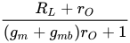
The amplifier characteristics are summarized below in Table 1. The approximate expressions use the assumptions (usually accurate) rO >> RL and gmrO >> 1.
| Table 1 | Definition | Expression | Approximate expression |
|---|---|---|---|
| Short-circuit current gain | 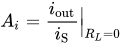 |
 |
|
| Open-circuit voltage gain | 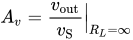 |
 |
 |
| Input resistance |  |
 |
 |
| Output resistance |  |
 |
 |
In general, the overall voltage/current gain may be substantially less than the open/short circuit gains listed above (depending on the source and load resistances) due to the loading effect.
Closed circuit voltage gain
Taking input and output loading into consideration, the closed circuit voltage gain (that is, the gain with load RL and source with resistance RS both attached) of the common gate can be written as:
,
which has the simple limiting forms
,
depending upon whether gmRS is much larger or much smaller than one.
In the first case the circuit acts as a current follower, as understood as follows: for RS >> 1/gm the voltage source can be replaced by its Norton equivalent with Norton current vThév / RS and parallel Norton resistance RS. Because the amplifier input resistance is small, the driver delivers by current division a current vThév / RS to the amplifier. The current gain is unity, so the same current is delivered to the output load RL, producing by Ohm's law an output voltage vout = vThévRL / RS, that is, the first form of the voltage gain above.
In the second case RS << 1/gm and the Thévenin representation of the source is useful, producing the second form for the gain, typical of voltage amplifiers.
Because the input impedance of the common-gate amplifier is very low, the cascode amplifier often is used instead. The cascode places a common-source amplifier between the voltage driver and the common-gate circuit to permit voltage amplification using a driver with RS >> 1/gm.

Sources and credits
This article is adapted from the Wikipedia article “Common gate”, written by its contributors and licensed under CC BY-SA 4.0. Fathomly has changed the layout, removed citation markers, navigation and maintenance notices, and adjusted punctuation. This adapted version is shared under the same license. For references, see the original article.
Images, from Wikimedia Commons:
- Common Gate.svg by Jncraton, CC BY-SA 3.0
- Common gate hybrid pi.PNG by Brews ohare, CC BY-SA 4.0
- Common gate output resistance.PNG by Brews ohare, CC BY-SA 4.0
Fathomly is not affiliated with or endorsed by the Wikimedia Foundation. Spotted a problem? Tell us.

