Chopper (electronics)
Electromechanical device

In electronics, a chopper circuit is any of numerous types of electronic switching devices and circuits used in power control and signal applications. A chopper is a device that converts fixed DC input to a variable DC output voltage directly. Essentially, a chopper is an electronic switch that is used to interrupt one signal under the control of another.
In power electronics applications, since the switching element is either fully on or fully off, its losses are low and the circuit can provide high efficiency. However, the current supplied to the load is discontinuous and may require smoothing or a high switching frequency to avoid undesirable effects. In signal processing circuits, use of a chopper stabilizes a system against drift of electronic components; the original signal can be recovered after amplification or other processing by a synchronous demodulator that essentially un-does the "chopping" process.
01Comparison (step down chopper and step up chopper)
Comparison between step up and step down chopper:
| Step-down chopper | Step-up chopper | |
|---|---|---|
| Range of output voltage | 0 to V volts | V to +∞ volts |
| Position of chopper switch | In series with load | In parallel with load |
| Expression for output voltage | VL dc = D × V volts | Vo = V/(1, D) volts |
| External inductance | Not required | Required for boosting the output voltage |
| Use | For motoring operation, for motor load | For regenerative braking for motor load. |
| Type of chopper | Single quadrant | Single quadrant |
| Quadrant of operation | 1st quadrant | 1st quadrant |
| Applications | Motor speed control | Battery charging/voltage boosters |
02Applications
Chopper circuits are used in multiple applications, including:
- Switched mode power supplies, including DC to DC converters.
- Speed controllers for DC motors
- Driving brushless DC torque motors or stepper motors in actuators
- Class D electronic amplifiers
- Switched capacitor filters
- Variable-frequency drives
- D.C. voltage boosting
- Battery-operated electric cars
- Battery chargers
- Railway traction
- Lighting and lamp controls
03Control strategies
For all the chopper configurations operating from a fixed DC input voltage, the average value of the output voltage is controlled by periodic opening and closing of the switches used in the chopper circuit. The average output voltage can be controlled by different techniques namely:
- Pulse-width modulation
- Frequency modulation
- Variable frequency, variable pulse width
- CLC control
In pulse-width modulation the switches are turned on at a constant chopping frequency. The total time period of one cycle of output waveform is constant. The average output voltage is directly proportional to the ON time of chopper. The ratio of ON time to total time is defined as duty cycle. It can be varied between 0 and 1 or between 0 and 100%. Pulse-width modulation (PWM), or pulse-duration modulation (PDM), is a technique used to encode a message into a pulsing signal. Although this modulation technique can be used to encode information for transmission, its main use is to allow the control of the power supplied to electrical devices, especially to inertial loads such as motors. The average value of voltage (and current) fed to the load is controlled by turning the switch between supply and load on and off at a fast rate. The longer the switch is on compared to the off periods, the higher the total power supplied to the load. The PWM switching frequency has to be much higher than what would affect the load (the device that uses the power), which is to say that the resultant waveform perceived by the load must be as smooth as possible. Typically switching has to be done several times a minute in an electric stove, 120 Hz in a lamp dimmer, from few kilohertz (kHz) to tens of kHz for a motor drive and well into the tens or hundreds of kHz in audio amplifiers and computer power supplies.
In frequency modulation, pulses of a fixed amplitude and duration are generated and the average value of output is adjusted by changing how often the pulses are generated.
Variable pulse width and frequency combines both changes in the pulse width and repetition rate.
In current limit control (CLC) technique, duty cycle is controlled by controlling the load current between maximum and minimum values. The chopper is switched ON and OFF periodically so that the load current is maintained between predetermined maximum and minimum values.
04Chopper amplifiers
One classic use for a chopper circuit and where the term is still in use is in chopper amplifiers. These are DC amplifiers. Some types of signals that need amplifying can be so small that an incredibly high gain is required, but very high gain DC amplifiers are much harder to build with low offset and 
The input offset voltage of amplifiers becomes important when trying to amplify small signals with very high gain. Because this technique creates a very low input offset voltage amplifier, and because this input offset voltage does not change much with time and temperature, these techniques are also called "zero-drift" amplifiers (because there is no drift in input offset voltage with time and temperature). Related techniques that also give these zero-drift advantages are auto-zero and chopper-stabilized amplifiers.
Auto-zero amplifiers use a secondary auxiliary amplifier to correct the input offset voltage of a main amplifier. Chopper-stabilized amplifiers use a combination of auto-zero and chopper techniques to give some excellent DC precision specifications.
Some example chopper and auto-zero amplifiers are LTC2050, MAX4238/MAX4239 and OPA333.
05Formulas
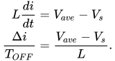
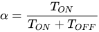
Step-up chopper
Take a general step-up chopper with voltage source 


and taking the average current within the turn-off time,

where 

where 
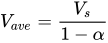
where
Step-down chopper
Taking a general step-down chopper with voltage source 

where 
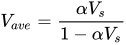
Step-up / step-down chopper
Taking a general buck-boost chopper which works as stepup and down chopper, let the voltage source
where
06Literature
- C. Enz, G. Temes, Circuit techniques for reducing the Effect of Op-Amp Imperfections: Autozeroing, Correlated Double Sampling and Chopper Stabilization - Proceedings of the IEEE, vol. 84 No. 11, Nov. 1996
- A. Bilotti, G. Monreal, Chopper-Stabilized Amplifiers with a Track-and-hold Signal Demodulator - Allegro Technical Paper STP 99-1
- A. Bakker, K. Thiele, J. Huijsing, A CMOS Nested-Chopper Instrumentation Amplifier with 100-nV Offset - IEEE J. Solid-State Circuits, vol. 35 No. 12, Dec 2000
Sources and credits
This article is adapted from the Wikipedia article “Chopper (electronics)”, written by its contributors and licensed under CC BY-SA 4.0. Fathomly has changed the layout, removed citation markers, navigation and maintenance notices, and adjusted punctuation. This adapted version is shared under the same license. For references, see the original article.
Images, from Wikimedia Commons:
Fathomly is not affiliated with or endorsed by the Wikimedia Foundation. Spotted a problem? Tell us.

